|
The Car
My 94 Ford Thunderbird SuperCoupe was a bit of a dream come true. It is one of those cars that captured my imagination as a fine piece of automotive engineering. Some guys like Corvettes, BMWs and Porsches, the Supercoupe seemed like an unpretentious practical car that could be driven without drawing undue attention. My "other car" is a red Mustang SVO that screams "ticket me!" even when it is parked.
Independent rear suspension, 4 wheel disks, adjustable ride control, ABS, positive traction rear and a 5 speed manual tranny in a well sized comfortable car where reasons other reasons I gravitated towards the SC. I do have a fascination with power adders and the oppertunity to work with a well engineered high boost factory setup excited me. The SC was the first recent auto to use a roots type blower in 1989. GM started using them also in 1992.
1994 or 1995 were the best years of these cars to buy in my opinion. These years have a better spindles, clutch, supercharger, throttle body and windage tray. They also come with slightly higher compression and floating wrist pins and a more direct exhaust path. Unfortunately not many were made with manual transmissions. 700 in 1994 and 500 in 1995, so they are modestly rare. Consider that some of the most desireable 60's supercars were only made in 500-5000 car batches to legitimize their attributes for various racing classes.
I purchased my SC unexpectantly in the late winter of 2002. I heard word of it at a local dealership on trade and slid in even before it underwent its pre-inspection. The price was high, the condition good, but I was disappointed when I drove it. Clutch engagement was rough (later found due to bad pilot bearing), idle was spotty, and engine was rough. A few seconds on boost brought serious rattle. I mentioned this to the salesman and that it shouldn't be driven until repaired. He said that it was to be pre-delivery inspected immediately and this would be repaired. I called a couple days later to find if it was ready and take my wife for a drive. The salesman said the engine problems were severe enough that they would not warranty the car because they did not want to fix it. My test drive did not go well. The engine now ran on 5 cylinders, smoked and blew oil out everywhere. Hey, bargaining chip!
Well the dealership (Cornwallis Motors, New Minas) didn't drop very much, and then later pulled a scam where they hit me with a $150 "Administration Fee" after I had paid my deposit, on a used car with no warrantee! I've never paid an administration fee on even my new cars. Administration fees are negotiable and are usually reserved for special work such as arranging financing or papering your trade in to a ready purchaser so you avoid taxes. These guys are crooks. I bought anyway, or lose my deposit and gain a big fight for nothing in hand. I paid more for this car than any other used car I have ever bought, and the motor was blown (in both ways!).
The car is black (I'd have prefered a silver, white or metalic blue) with tan leather and most options.
Engine, Removal:
This is a tough motor to remove. The cowl and windshield wiper assembly all has to come off and the supercharger and all its ducting had to be removed so the engine could be lifted high enough to clear the oilpan/crossmember hump. The front subframe could have been lowered 4" to remove the motor intact without touching the cowl but it is debatable which would be more work. Pulled the powersteering pulley off to access the bolts behind it and tucked the pump off to the side, as with the air conditioner compresser. The driver's side exhaust manifold studs were nightmares due to the heat shield that limited access. I drilled/ground the little screws that held the shield to remove it for access through the wheelwell. Also the driver's side motor mount has a frame bolt that usually has the nut freewheel as you try to remove it. I torched it. Tricky spot for this however.
There are LOTS of bolts to keep track of. Laying them out in punched holes on a cardboard schematic of the motor and in little ziplocked bags really helped organize things. Masking tape and a marker is a wonderful way of marking things for reassembly many weeks later. A digital camera is a good idea too. Pressure washing before and during removal made the job much more enjoyable. Watch where you spray, I have seen this tool destroy a lot of dollars of bearings, seals and decals. take steps to prevent rust on bare metal.
I found the fluid filled transmission mount leaked. It squirted oil into my face when I pressed on it! The fluid filled motor mounts were fine but these usually have a 10 year lifespan and we are on year 8. Lots of rocks and gravel tucked away in the recesses, some rust too. A little brush and paint will make nice.
The Engine, autopsy:
Engines are my thing. I love them. Every engine I tear apart gets my thorough examination. Every engine I put together gets my full love and attention. I am not a professional engine rebuilder but I have rebuild or done major work on several a year since 1975. Even my Briggs&Stratton rototiller got a porting job and I tuned the homemade header on my lawnmower for maximum torque in the heavy grass. I read everything I can on the sport and experiment whenever the opportunity arises. I did take a year of Automotive Tech many years ago. My base trades are as a machinist, industrial mechanic and electrician with some electronics background. This has been a help with my passion for all things mechanical and EFI motors in particular.
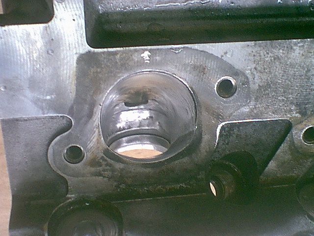
Well, the engine she died of a broken heart. Number 6 piston was blasted by detonation centered under the intake valve. Both valves were bent and the piston was cut like by a torch along the side. The upper ring was intact but the lower was cut. Whether injector or ignition is the cause has not been determined as of yet. New injector and wires will be installed of course. The rod bearing also showed signs of detonation damage but the rod and all other bearings were in fine shape, didn't really need replacement. You could still see the crosshatching on all the cylinders but there was slight scuffing on #6. The headgasket on #6 was near failure from having the fire-ring pushed out from the detonation. Both heads and block decks were modestly unlevel to about 0.005", high at bolt holes. Accepable but not good, both will be surfaced. The valves seats except for #6 were in fine shape. There was slight wear on the rockerarm fulcrums but elsewhere everything was excellent. Little sediment indicated the engine was well cared for and blowdown was fine in the other 5 cylinders. The engine could be repaired with a replacement of only #6 rings, piston and rod bearing if I wished.
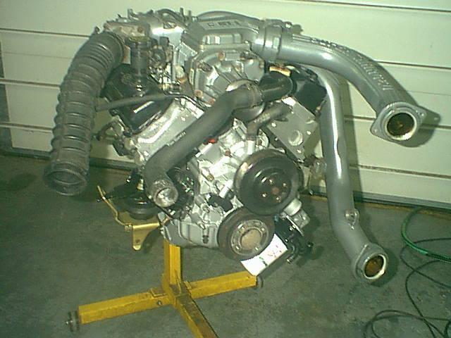
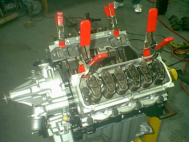
| Longblock without front accessories |
|
| Colours are metalic iron and Hammertone aluminum |
Engine, block rebuild:
The main problems with my block were the slightly scuffed #6 cylinder and the unlevel deck surfaces. It pressure washed up just fine and the cam bearings were excellent. I sprayed it with Fluid Film as a rust preventative.
All the cylinders were honed with a #500 grit Sunnen parallel hone, opening up the clearances to about 0.003" with a nice crosshatch finish. I buffed the scuffed secions of #6 cylinder with a fine flapwheel for their entire height, trying to draw the bore over in that direction a thou or two, then honed it too. I ended up with about 0.005" clearance on #6 with a stock size piston. There is a 0.005" oversize piston that would have been a good idea for this cylinder, but it pretty much cleaned up at this so I opted for stock size.
The deck was very wavy, high at the bolt holes and low between the cylinder bores. I hand filed it. Before you scoff, understand that part of my machinist training is to file precise surface finishes and sizes. I might have done it with the heads too if it wasn't so cheap to get a perfect job done. Decking a block is pricy. Use a 12" hand bastard file and a light cross hatch pattern to get a nice job. Measure to a bar in the crank saddle if you want to know level (for even compression). My block was level and even so a little cleanup was all that was needed.
The crank was perfect, so why mess with it? I don't even like the thoughts of polising them if there is no problems. All the rods including #6 were fine. I deburred the block, inside and out, tapped everything and took the rifle brushes to it. Frost plugs were solid so they weren't touched. Sometimes if something ain't broke you shouldn't mess with it. Everything was pressure washed again and chased with varsol to dry. The block was painted.
The crank was fitted and I found a problem. The rear main takes a 0.010" undersize bearing and there was only one in the TRW box! It was Friday and wanted to get this done, the removed bearings were like new so I installed one used shell. Clearance was 0.002"-0.0025" on all. Blue locktited and torqued the mains, sliding the crank on Lubriplate. The chain was well within specs so reused it. Gotta love a tensioner! The stock cam was used straight up. Oil pump and passages were massaged a bit and special thanks to Dr Fred Holzhauer for clueing me in on how to time the cam sensor.
Rods and pistons installed and red high strength locktite used on their bolts. Nasty incidents over the years have made me a believer in locktite and constant use of the torque wrench. Again, everything was Lubriplated heavily including the oil passages. Lubriplate is basically a thickened oil that will say in place for months but melt away with oil and heat. Better than oils, better than greases for engine assembly. Prime the oil pump and pickup tube with it.
One note about the timing cover, the water pump passages neck down from over 1" to less than 7/8ths with a nasty flashline. Overheating and headgasket failure are problems with these engines so I reasoned that waterflow should be crucial. I ported out and matched the timing cover just like I would an intake port. After all, porting is even more effective with this more viscous fluid. I ported the head and intake water passages as well, but there is a bottleneck at the thermostat housing.
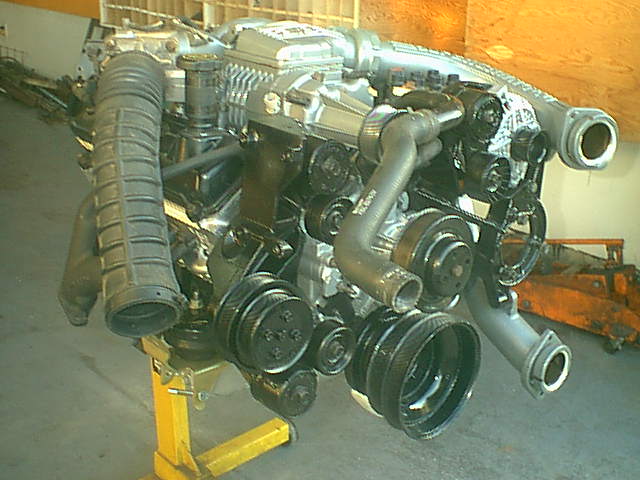
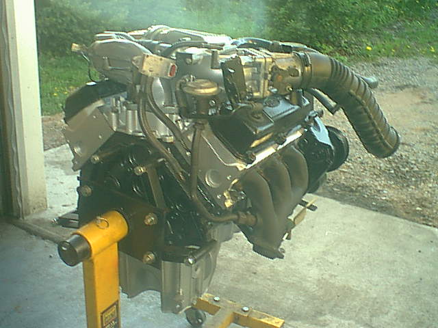
| Longblock with front accessories |
|
| Ported and gasket matched intake port, no polish |
|
| Note the 2 different ports. |
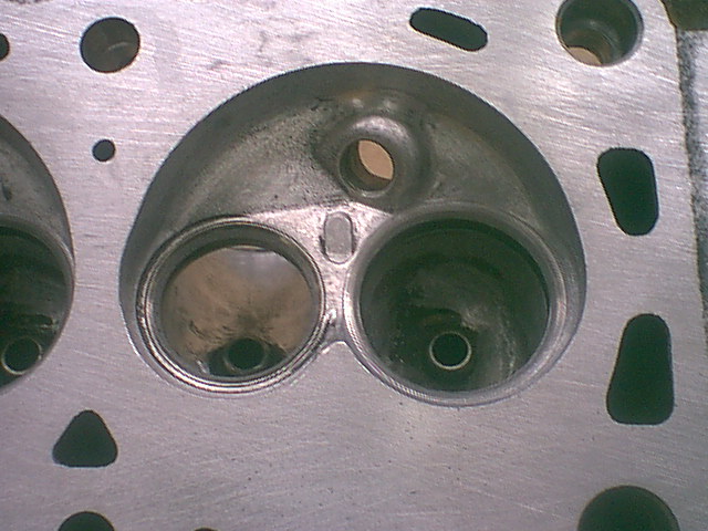
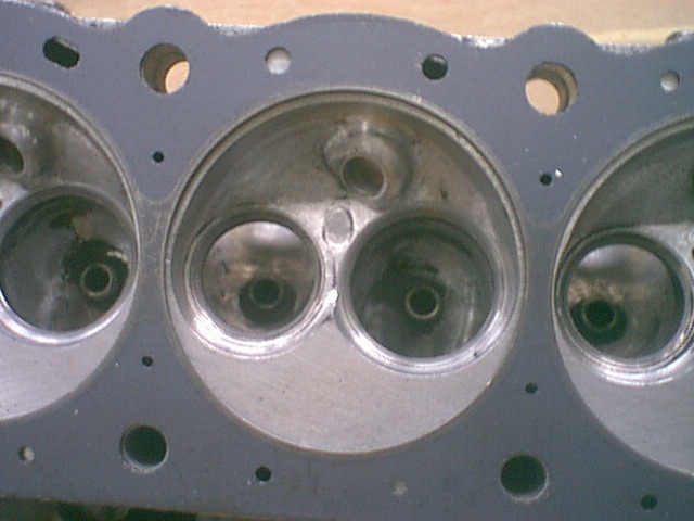
Engine, Intake porting:
Here is where performance is built. I do not have much experience with the SC, but I do with other engines. There is not much info on porting the 3.8L Essex heads. I conservatively ported a Taurus last year using intuition and experience, and noted an improvement in top end with no loss of bottom end torque. I magnified on these ideas on my SC heads. The internet provided pictures of some other folk's ideas on porting these heads, some of them professionals at it. Pete Henderson builds a pretty darned successful drag and rally Chevy smallblock and was kind enough to make recommendations on the port and chamber work.
The plan is to have a slight funnel sized port from the intake manifold to the valve opening. In fact, it funnels the opposite way! The intake manifold port opening is smaller than the valve opening. A lot of careful measuring with the dividers and calipers, and some math, figured the amounts of metal to take off to have a gradually decreasing port size. Most of the metal came off the roof and outer (from the cylinder's point of view) side of the port. The swirl path was maintained and enlarged. The ports were all matched to the smallest gasket opening, the center one. At the gasket face you MUST have a near exact match and the head should be ever so slightly larger than the intake opening. The factory aims for 0.100" larger, I aim for 0.020" on the sides and 0.050 on the roof and floor where there is more potential for mismatch. I know this is opposite of the way you want to funnel but it is to avoid protusions into the flow. For this reason also DON'T USE RTV SILICONE on the intake or most other gaskets. Use them dry or use an anerobic hardening sealer that doesn't hump up at the joint.
There is only about 0.100" of metal between the intake port and the pushrod tubes and headbolt holes, so don't go too far with the porting. If you are not going to open up the port over the valve, don't bother to open up the face. You'll need some long cutters, the ports are about 4" deep. You should maintain a consistant area through the port, not big cavities. The area decrease toward the valve should be very gradual. The center "dogleg" port presents some challenges. Be very careful of how you remove metal here. Best to brush up on how air flows in "S" section pipes. Don't touch the floor other than to smooth the short radius and match the gasket face. I build up bolts to precisely fit and line up the gasket holes. When installed the intake gasket will be glued to the head to maintain its close relationship while the intake is torqued down.
While on the subject of the intake face, I must mention I ported the front water port as well. I matched it to the gasket but unlike the intake port it must be kept undersize of the gasket as the water flows out of the head. Since I have marked the heads RIGHT and LEFT and intend to keep them that way, I only ported the front water ports, the rears are blocked off.
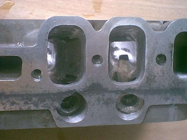
| Stock exhaust port |
|
| From Bob Stiegemeier Racing Heads http://members.telocity.com/~bjherron/scheads/index.htm |
Click on the picture above to see a larger version of the rough stock ports, OR click on this link to see Bob Stiegemeier's wonderous head work. Wish I had found this site BEFORE I started grinding... Note the bulge in the right side, the sharp short radius edges, and the odd cuts and pockets. The guide "shelf" is actually smaller on this engine than it was on mine.
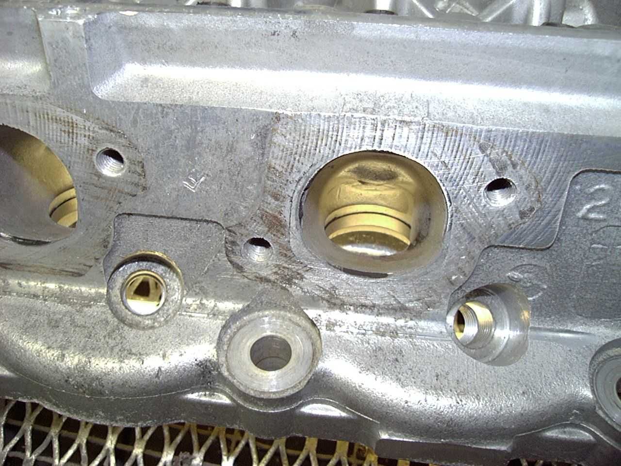
| Ported and polished exhaust port |
|
| Straight view to the valve |
Engine, exhaust porting:
The exhaust port looks like a real mess to my eyes. Great proturbances extend out on the inner side of the port under the valve and there is a large shelf that the guide sleeve sits on. The short radius (like on the intake) is a sharp right angle. From this tight bowl area the exhaust port expands to a generously oversized manifold face opening which it meets at a strong angle. The exhaust manifold is itself oversize of the port, which is good, but quickly pinches in to give room for the bolts. The manifold greets the port straight on so that there is an angular mismatch of the ports here.
In contrast to the intake port the exhaust was radically reworked. The pinch in on the inner side was removed to be a straight line from bowl to face. The outer side was opened up slightly but most material was removed only from the bowl area. Only the short radius on the floor was reworked, smoothly radiused. The rest of the floor was untouched. The largest work was done removing the shelf that the guide sits on. It was completely removed and around the guide streamlined.
Right off the start I aimed for a gentle roof curve from the back of the bowl to the manifold face so that I would get a right angle at the face. This involved a template and very careful grinding to get it that same on all ports and to minimize the amount of material removed. The roof of the exhaust is one of the most blasted areas on the head so we don't want it too thin here. The entire port was polished to a glassy smoothness to reflect heat and shake off carbon buildup. The opening at the exhaust manifold was untouched. It is plenty large and decidedly smaller than the manifold and the mismatch is desired for its anti-reversion effects.
| Polished and unshrouded chamber |
|
| Note open radius around intake valve and wall side of ex |
| Unshrouded chamber within headgasket |
|
| Notice open room all around both valves |
Head, Chamber:
The chamber is unusual in that it has a large quench area but that the valves are sunk deep in the chamber to get the large chamber volume needed for a low compression supercharged engine. This shrouds the valves but seems to serve a purpose to build swirl, needed for emissions and burn rate purposes. One half of the intake valve is tightly shrouded for half of its diameter and half of its lift, which is more than 1/3rd of its area/time open window. The exhaust shrouding is much better but is closed in rather tightly by the cylinder wall. As the piston comes up to push the exhaust gasses out it is nice to have a smooth transition from cylinder wall to chamber with minimal lip except at the quench.
I made up a cutter from an old valve to radius the intake shrouding out to almost the cylinder wall. This was about a .25" radius that came up at right angles on the quench face to maintain swirl. I used a similar cutter on the exhaust side to cut the radius out to the cylinder wall. The exhaust cutter did not remove any metal from the quench side, just next to the cylinder. The valve guides have to be well cleaned and lubed to protect them from wear and chatter. The beauty of a cutter is that every cylinder is exactly the same as the other.
Engine, Valves and seats:
All the valves were highly polished. Even though the surface treatment removed may have some special heat characteristics, the polish reflects heat and resists carbon buildup. The lip on the exhaust valve has to be maintained for anti-reversion purposes. I can tell you from experience with it on Windsors that removing it will kill low end torque. The chamber was polished and the valves lapped. The exhaust valves were left with only the wide 45 degree face to maximize cooling. The intake valves recieved a 30 degree back cut. 30 degree angles were cut on the valve faces up to the lapped surface and a 60 degree angle to get a 0.060"-0100" seal.
An interesting sidebar to the wide valve seat faces needed for turbocharging and supercharging is that they are intolerant of dirt. The slightest bit of dirt will hold the valve open and pit the face, whereas a narrow 44+45 degree is very tolerant of dirt. This means better filtering is needed for these wide lapped valve seat engines, as well as for protection of the power-adder itself. This makes constant use of a K&N filter questionable for engine and supercharger longevity.
At this point the heads were planed, cleaned, assembled and all the old sparkplugs were reinstalled. A CC plate was installed over the chamber and ATF was measured in with a syringe to make sure each chamber was within a CC of the other. The same was done to the cylinders after each cylinder was dialed in to top dead center. The small chamber/cylinder combos recieved a bit more buffing and polishing. Consistant port flow and compression ratio is important to minimize detonation and maximize power potential, as the engine will have to be tuned/detuned to the most detonation prone cylinder. Port flow can be compared with a shopvac and a length of waterfilled clear hose looped to the ceiling as a manometer.
The heads were torqued in place with perfectly clean deck surfaces. Aluminum head cast iron block engines need a little slide in the headgaskets to allow for the different expansion rates of the two metals. The gaskets have a graphite, teflon or silicone coating and require a smooth head and block surface to slide while sealing. Use no sealers! New bolts were used and the heads torqued to specs.
About head studs and cylinder "O" rings:
I have used both on engines over the years and while they both work as advertized, there are compelling reasons to NOT use them on a street driven engine. First of all, both complicate head work and take special care by an informed mechanic. If your car should burn a valve or blow a gasket when miles from home, expect to pay a BIG premium for a shop to deal with head studs and cylinder "O" rings.
With head studs either the engine has to be removed or each stud removed before the heads can be removed in-car. "O" rings in the head tend to weaken the deck surface, in the block tend to brinnell their pattern into the heads and tend to promote headgasket leaks if they are left out on an emergency repair. (How do I know this stuff?!!)
Moreover, most headgasket leaks are not the fault of the gasket seal or the bolt stretch. Most headgasket leaks are caused by:
1) Warpage caused by overheat or stress relief over time
2) Excessive compression spikes form detonation, ie: knock
3) Gasket core and ring breakdown from movement fatigue
4) Corrosion from poor coolant protection
Detonation is a common cause of headgasket failure on performance engines. Head studs and cylinder "O" rings will not cure the root causes of any of these problems although they may continue to seal in spite of them. The problem is if you do not cure the detonation, it will be the pistons, rods and bearings that fail. The headgasket is the safety valve, the "shear pin" if you will, to tell you you have a long term tuning problem, and save your bottom end. Assuming that your engine did not hydrolock or drink too much coolant in the oil.
Unless you are making huge cylinder pressure or using huge amounts of boost head studs and cylinder "O" rings are more problems than they are worth.
| Ported exhaust manifolds |
|
| Inlet opened to 1", outlet bored to 2" and blended |
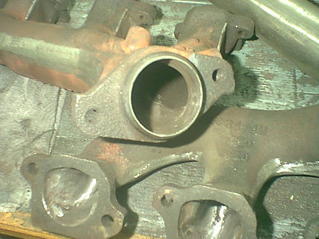
Engine, Exhaust manifold:
Headers for this engine were bloody expensive and would be a nightmare for retorquing. As well, the cast iron manifolds were not that bad a design, every bit as good as the old Corvette and 289 HiPo manifolds we looked for back in the 70s. The worst points on them were they are pinched in for the bolts and the small 1.75" exit. The exit is rather interesting as it is a neck down from 2" in about an inch up the manifold.
I ground the entrance smooth and opened up the pinch point from 7/8ths to 1" between the lumps, and bored the exit to 2" on the milling machine. Setting up for the double angle of these hard to hold manifolds was a chore. The interior was blended, smoothed and polished as far as I could reach with the die grinder. I ground off the casting flash for no other reason than esthetics (like anyone will see them!) and painted them inside and out with black BBQ paint over HighTemp Aluminum and baked them. I was interested in ceramic coating as I have been impressed with its performance on headers, but the turnaround time was too long by the time I found a Canadian supplier.
| Intake gaskets being glued on prior to porting |
|
| Single drop on superglue at both ends, intake will be torqued |
Engine, intake manifold:
While matching and blending the intake ports was not too huge a task, seeing as there is no problem if you go slightly oversize, the intake manifold presents some real challenges. Look at the heads and you will see that each surface, top, bottom, and sides, all meet the gasket face at an angle. It would be nice to match these angles as well as keeping slightly under the sizes. The intake gasket was doweled to the manifold and the ports were rough scribed to approximately 0.100" undersize. By means of a minature machinist's protractor (angle transfer) the angles were ground into the intake manifold ports as far as needed. The front water ports can be opened up to the size of the gasket or larger. Now the hard part. Transfering the port sizes for a perfect match:
Ideally each intake port would be an identical size and shape but unfortunately the 3.8L has an oddball center port. This is not the end of it, each port hole cut in the Ford gasket is a different size, so hopefully you didn't just port out the head to match the gasket. Now if you set the manifold on the long block and thread the bolts in loose, you'll notice the manifold can slide back and forth about 0.040-0.060"! So if you port the intake as an exact match and just slap it on you'll be sure to have a miss-match. We have to get more accurate than that.
As for the intake manifold inlet, it can be opened up to the size of the gasket or slightly larger, allowing for the slop of the bolt holes. Like all porting it should be opened up parallel and blended into the inner opening.
One method is to line the gasket up on the heads, hold them in place with a drop of superglue on each end and install and torque the manifold in place. Here some folks will drill each corner of the manifold for a small pin, preferably tapered but a 1/8th straight pin will work. I prefer to carefully scribe out the manifold outline on the bits of the gasket that overhangs. Now the manifold comes off and I carefully cut the gaskets (marked left and right) off the heads with a razor blade. With the scribe lines carefully lined up on the manifold the gasket is clamped in place and the port outline can be scribed on the intake manifold faces. Keeping in mind the size difference needed and angle, about half the wiggle in the bolts is good for the sides and 150-200% of that for the top and bottom since it is hard to predict how deep the manifold will wedge in. I can grind the intake manifold to the precise fit I need. To install the intake manifold the gaskets are again glued to the heads, perhaps heavier this time, with the drops of superglue or contact cement and the intake installed carefully lined up with the scribe lines. Intake gaskets can be installed dry and perhaps should be since that is how you torqued it to line it up. Remember that a "squishy" sealant like silicone rubber will bead up and ruin your fine port matching job. Anerobic sealer like sold by Loktite or Aviation Gasket Sealer by Permatex are my favourites.
I think I have rambled on enough about gasket matching and porting. If you get what I am saying here you'll have no problems with the principles of what I did to match up the various plenums and the blower itself. One thing to keep in mind is that everything after the blower is pressurized up to double atmosphere so it can be half the area as the intake for the same flow. Unfortunately the intake ducting isn't that large. The whole plan is to keep the area of all ducting close to constant. The slower the flow, the less critical the streamlining. The ducting leading to the supercharger is the most critical, since restriction here will lead to cavitation and pump (rotor) damage. I suppose it should be kept in mind that a 70mm throttle body flows more than a 850cfm carb at the same pressure drop, but the larger the bore the less the pressure drop and the more power in all cases, everything being equal. Air/fuel mixtures need velocity to keep the fuel in suspension but luckily for EFI we only have the last 3" of the porting to worry about that.
Engine, Final assembly:
Whew! It was a lot of fussy work getting to this point. I thought I was very meticulious in laying out and storing my bolts and various pieces. Well, being layed up 2 months while a 454 was rebuilt, installed and tuned, a little Chevy headgasketed, several Scout projects, a Bronco disembowled, and other various interuptions meant the hardware was shoved around a lot and my memory grew fuzzy. I was a whole day finding pieces and getting the front accessory dress painted up and installed on the engine. Sheesh, I was half a day tearing the shop apart looking for my $100 transmission mount. My young fella, not knowing what it was, had placed it behind some chain saws under a shelf while cleaning up the shop for Dad. What can you say?
No tricks here, I just put her back together by the book, getting the right fasteners in the right holes. I left the bottom pulley and harmonic balancer and oil filter off so they wouldn't be damaged on installation. I did install new motor and transmission mounts. I am aiming for more power but I opted for the fluid filled mounts because I do want a comfortable fast car, not a firebreathing monster. While much discredit has been cast about the reliability of the fluid mounts mine did last 8 years and I really don't want any vibrations in this car. I do have an SVO for when I want a nasty bad boy infusion. If the mounts break, I'll replace them with tougher I guess. Stay tuned...
One of my tensioner pulleys had a stiff noisy bearing that was likely soon to fail. Thanks to Sean Matteson I was to learn that Canadian Tire has a lovely steel replacement for the plasic pulley. Just ask for Dayco #XXXXX and expect to pay about $22. I only replaced the one and put it on the bottom at the top tensioners would be easy to detect and replace if needed.
From 1989 to 1993 the SuperCoupes had an oil level sensor in the oil pan. I also have this feature on my 1986 SVO and feel it is worthwhile in a boosted engine. I had a PCV checkvalve fail on my SVO and managed to blow over a liter of oil out of the engine in just a few seconds of boost. An oil sensor would detect the loss of oil before any engine damage was done, unlike a pressure guage or switch. On the SuperCoupes this expensive sensor has a second value as an oil temperature sensor, although it reads back only to the computer on the pre93 cars. It was left off the 94-95 cars, probably as a cost saving measure. To install it on the 94 the oilpan had to be tapped M20x1.50 and the wiring to a light and a guage.
| Rear view of 3.8L supercharged SuperCoupe engine |
|
| Note the smooth exhausts, oil level sender not installed yet |
The car:
Like any 8 year old car up here in the rustbelt, she has some spots on her underbelly. While the motor is out I am buffing up the odd spot in her bay and floor, primed with zinc chromate and giving everything a coat of shiny black. The original primer and bottom colour is actually a matt dark grey, but who'll know?
|